WARNING
Connection to air supply starts spindle rotation. Do not connect air to your tool until installation is complete.
Read all instructions thoroughly before installation and use.
Downloadable PDF Content
Mounting Air Turbine Spindles® in your CNC
You have three options for mounting your Air Turbine Spindle® to your CNC machine.
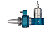
- Side or Rear Air Inlet
- Thru-toolholder air supply
- Tool Changer Mounting Assembly
Your spindle has 2 air inlets (rear + side), and it is important that the inlet that is not being used is closed. If you hear a loud noise or have underrated power performance, ensure that the unused inlet is properly plugged. If necessary, use magnets for temporary mounting during set up.
1.
Side or Rear Air Inlet
2.
Thru-Toolholder Air Supply
3.
Tool Changer Mounting Assembly (ATC)
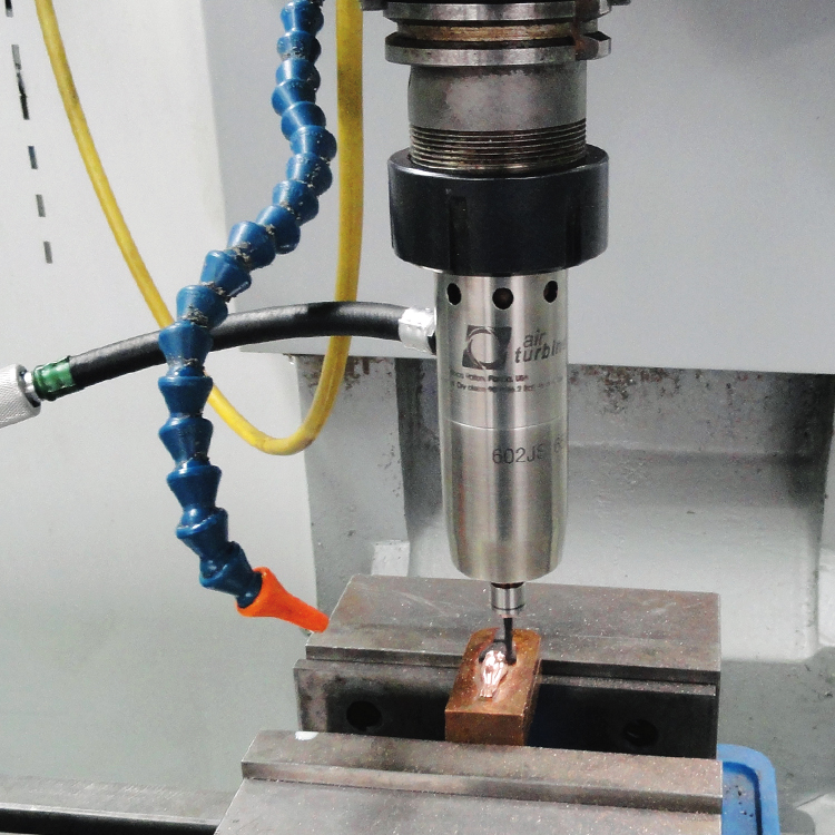
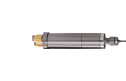
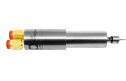
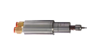
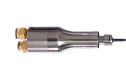
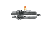
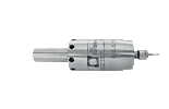
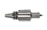
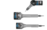
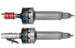
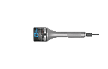
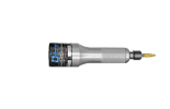
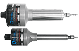
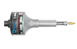
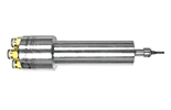
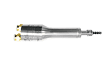
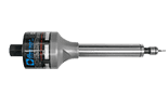
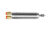
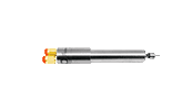
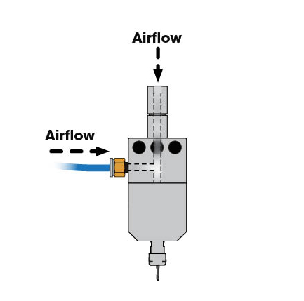
1. Side or Rear Air Inlet
The 600X, 601, 602, 625 and 625X series of Air Turbine Spindles® have selectable rear or side inlet options. JS units combine with ER32 or other toolholders for infinite compatibility.
650JS and 650XJS models only use the side inlet for air supply.
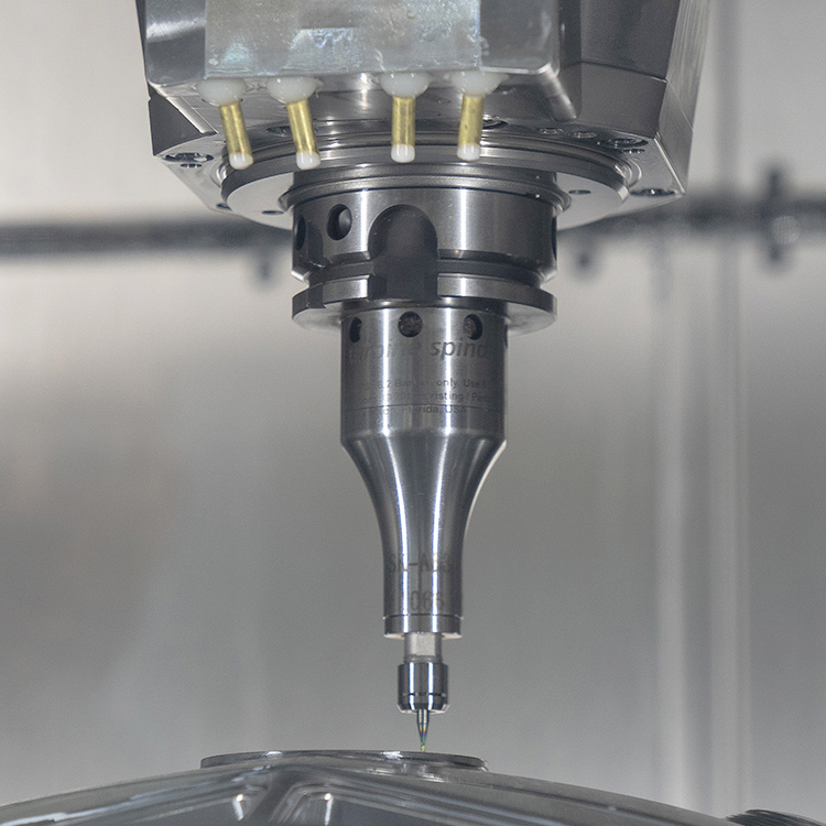
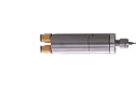
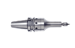
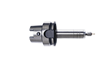
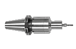
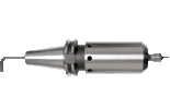
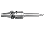
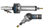
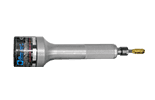
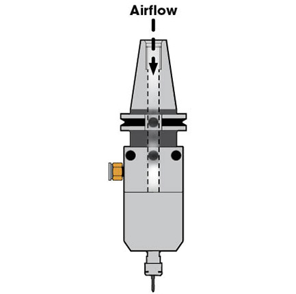
2. Thru-Toolholder Air Supply
To supply Thru-Spindle-Air (TSA) to power to Air Turbine Spindles®, verify the maximum CFM (L/s) flow possible through the air channel and determine the maximum drawbar/pull stud/internal hose internal diameter in the system, including any solenoid used to actuate the air.
Some retention knobs can be drilled to enlarge the opening and permit the proper flow as specified in figure 3. The channel must be clean with no part smaller than the minimum internal diameter as specified for your model in the table in figure 2 so that air volume is unrestricted. Purge the line before use.
All HSK spindles may be used with the center air feed if the airline and all connectors meet the minimum internal diameter requirements stated for your model in figure 2.
TECHNICAL NOTICE
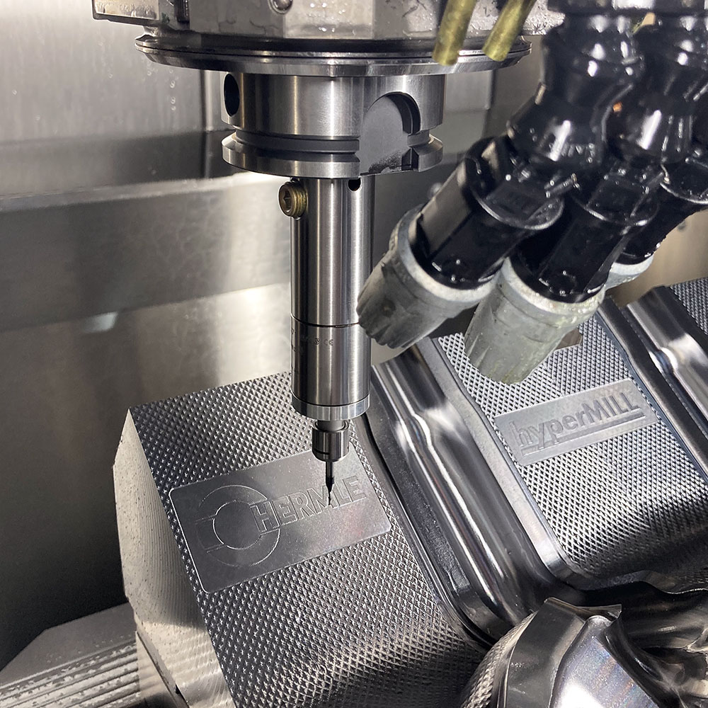
Certain CNC machines, such as Hermle, include a “Perlman valve”, which restricts airflow pressure to 30 psi / 3 bar air. This pressure is below the minimum required 90 psi / 6.2 bar pressure required for operation of Air Turbine Spindles®.
This valve must be removed for the proper operation of Air Turbine Spindles®. Please consult with your machine’s technician to ensure that there are no restrictions of air flow. Failure to remove this valve will cause a flow restriction, under power performance and cause damage to your Air Turbine Spindle®.
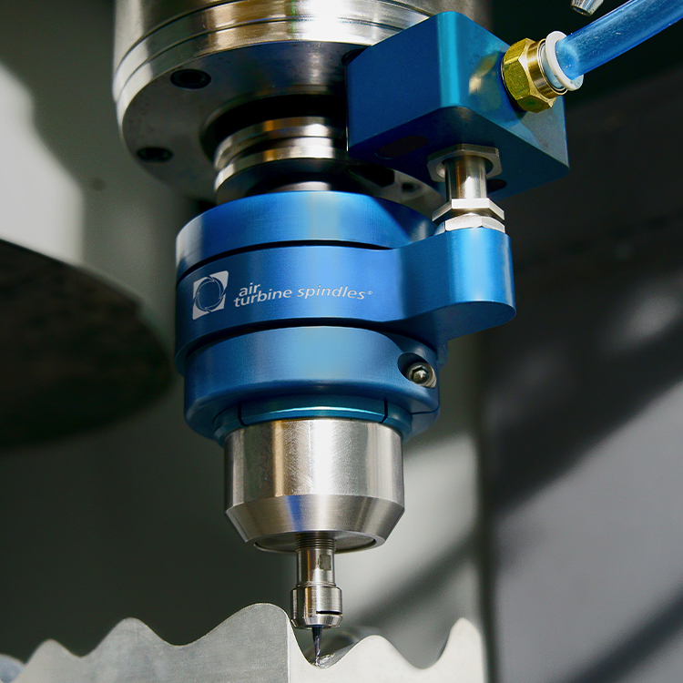
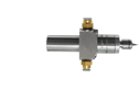
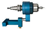
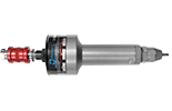
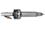
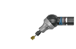
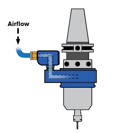
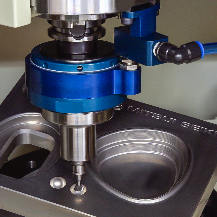
3. Tool Changer Mounting Assembly (ATC)
Our patented wrap-around Tool Changer Mounting Assembly (TMA) option allows CNC tool-changers to automatically load/unload our family of high-speed precision spindles using a proprietary collar system and mounting block or a ring around the CNC spindle, the TMA collar orientates integrating to the right side of the CNC spindle in minutes. The TMA block remains on the CNC spindle for normal tool changes, even if not using the Air Turbine Spindle® as it will not interfere when using the main spindle.
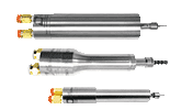
There are three main types of Tool Changer Mounting Assemblies as shown below to be compatible with Haas, Hurco, Doosan, Robodrill, Hardinge, DMG, Brother, Okuma, and all other CNC’s. We are accustomed to developing custom solutions for any CNC. A universal block can also be provided for drilling your CNC screw positions. Installation kits are available.
Screw In Mounting Block
Two Piece Ring and Block
Drill Tap
Initial Installation
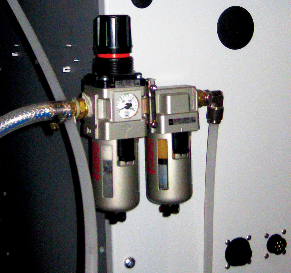
Mount your Air Turbine Spindle® into your CNC machine and install a new dedicated clean air line from a filter/regulator to your Air Turbine Spindle® as shown in figure 1. Filter/regulators are included with your spindle and are available for an additional purchase.
Ensure all air lines and fittings meet the minimum internal diameter specified for your model, as specified in figure 2. Additionally, place a plug in any air inlet that is not being used.
Optional: If you have a manual shut-off valve, install it after the filter/regulator as shown in figure 1. Using a manual valve is recommended.
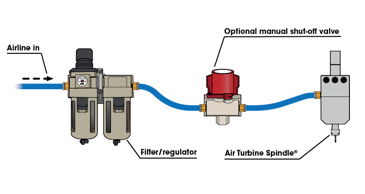
Figure 1: A clean airline from a filter/regulator to a manual shut-off valve to an Air Turbine Spindle®.
Air Hoses and Fittings Requirements
Avoid fittings, couplings and hoses with a smaller internal diameter than the minimum required for your model. Any connections smaller than the minimum will restrict air flow and reduce power to your Air Turbine Spindle®. You can find the minimum required internal diameter (ID) for fittings and hoses for your tool on the table shown in figure 2.
Air flow restrictions (such as air leaks and obstructions) will cause underpower performance and drag your tool through the material, damaging the bearings. Some fittings with nominal internal dimensions may have an ID passage that is smaller than stated and restrict air flow and power. It only takes one fitting with an internal diameter that is too small to reduce air flow and power of your Air Turbine Spindle®.
WARNING
Your Air Turbine Spindle® must be run at least 10 minutes every 30 days from manufacture date to maintain optimal performance. Run at least 10 minutes before initial use.
Your Air Turbine Spindle® must be run at least 10 minutes every 30 days from manufacture date to maintain optimal performance. Run at least 10 minutes before initial use.
| Air Hoses and Fittings Requirements for Air Turbine Spindles® | ||
| Model | Hose/Connector Minimum Required Internal Diameter | |
| Metric | Imperial | |
| 4 mm | 5/32” |
| 6 mm | 15/64” |
| 8 mm | 5/16” |
| 10 mm | 25/64" |
| Air Hoses and Fittings Requirements for Air Turbine Spindles® |
| Model |
|
|
|
|
| Hose/Connector Minimum Required Internal Diameter | |
| Metric | Imperial |
| 4 mm | 5/32” |
| 6 mm | 15/64” |
| 8 mm | 5/16” |
| 10 mm | 25/64" |
Figure 2: Air Turbine Spindles® hose/fitting/connector internal diameter specifications.
Air Requirements
Ensure there is sufficient volume of clean compressed air flow at 90 psi/6.2 bar with the specified air flow volume CFM (L/s) for your model as shown in the table in figure 3 to maintain working air consumption. Depending on application, consider peak or stall capacity consumption. Our governor increases air flow volume on demand to keep rotation at the high speed when your tool starts to cut. Air pressure and flow volume must therefore be available on demand and remain constant with no drop over time or when cutting.
WARNING
Connection to air supply starts spindle rotation. Do not connect air to your tool until installation is complete.
Connection to air supply starts spindle rotation. Do not connect air to your tool until installation is complete.
Do not oil or lubricate. Use dry, clean, oil free 90 psi (6.2 bar) air supply only.
Avoid pressure below 90 psi (6.2 bar), which causes the tool to be dragged through the material, causing rapid bearing wear and underpowered performance. Do not use more than 100 psi (6.9 bar) pressure which will burst the turbine power producer.
Air pressure and flow must remain constant with no drops under cutting load. Insufficient flow will cause the rotation of your tool to slow or stop suddenly, damaging the bearings. If a drop in psi (bar) occurs below 90 psi (6.2 bar), your compressor may not have enough CFM (L/s) to power the Air Turbine Spindle® or there is a flow restriction in the air line.
Idle CFM/L/s Rating vs. Working Air Consumption Ratings
Air Turbine Spindles® consume more air as the cutting load or the amount of material removed increases. This is normal operation of our patented governor which maintains high speed on your tool path and makes Air Turbine Spindles® efficient in air consumption.
| Air Turbine Spindles® Idle and Working Air Consumption Ratings |
|||
| Model | Speed | Air Consumption Idle | Air Consumption Working Flow |
| 65,000 RPM | 3.5 CFM (1.65 L/s) | 5 CFM (2.36 L/s) |
| 80,000 RPM | |||
| 40,000 RPM | 4.5 CFM (2.1 L/s) | 5 CFM - 6 CFM (2.26 L/s - 2.83 L/s) |
| 50,000 RPM | |||
| 65,000 RPM | |||
| 90,000 RPM | 5 CFM (2.36 L/s) | ||
| 30,000 RPM | 12 CFM (5.66 L/s) | 11 CFM - 20 CFM (5.19 L/s - 9.44 L/s) |
| 40,000 RPM | 14 CFM (6.61 L/s) | ||
| 50,000 RPM | |||
| 65,000 RPM | 16 CFM (7.55 L/s) | ||
| 30,000 RPM | 16 CFM (7.55 L/s) | 22 CFM - 30 CFM (10.38 L/s - 14.16 L/s) |
| 40,000 RPM | 20 CFM (9.44 L/s) | ||
| 50,000 RPM | |||
| 30,000 RPM - 50,000 RPM | 12 CFM (5.66 L/s) - 20 CFM (9.44 L/s) | 11 CFM - 30 CFM (5.19 L/s - 14.16 L/s) |
| 25,000 RPM | 13 CFM (6.14 L/s) | 14 CFM - 35 CFM (6.61 L/s - 16.52 L/s) |
| 30,000 RPM | 18 CFM (6.49 L/s) | ||
| 40,000 RPM | |||
| 25,000 RPM | 14 CFM (6.61 L/s) | 19 CFM - 40 CFM (8.97 L/s -18.89 L/s) |
| 30,000 RPM | 20 CFM (9.44 L/s) | ||
| 40,000 RPM | 23 CFM (10.85 L/s) | ||
| 25,000 RPM - 40,000 RPM | 13 CFM (6.14 L/s) - 23 CFM (10.85 L/s) | 14 CFM - 40 CFM (6.61 L/s - 18.89 L/s) |
| 50,000 RPM | 20 CFM (9.44 L/s) | 20 CFM - 35 CFM (9.44 L/s - 16.52 L/s) |
| Air Turbine Spindles® Idle and Working Air Consumption Ratings |
| Model |
|
|
|
|
|
|
|
|
|
| Speed | Air Consumption Idle | Air Consumption Working Flow |
| 65,000 RPM | 3.5 CFM (1.65 L/s) | 5 CFM (2.36 L/s) |
| 80,000 RPM | ||
| 40,000 RPM | 4.5 CFM (2.1 L/s) | 5 CFM - 6 CFM (2.26 L/s - 2.83 L/s) |
| 50,000 RPM | ||
| 65,000 RPM | ||
| 90,000 RPM | 5 CFM (2.36 L/s) | |
| 30,000 RPM | 12 CFM (5.66 L/s) | 11 CFM - 20 CFM (5.19 L/s - 9.44 L/s) |
| 40,000 RPM | 14 CFM (6.61 L/s) | |
| 50,000 RPM | ||
| 65,000 RPM | 16 CFM (7.55 L/s) | |
| 30,000 RPM | 16 CFM (7.55 L/s) | 22 CFM - 30 CFM (10.38 L/s - 14.16 L/s) |
| 40,000 RPM | 20 CFM (9.44 L/s) | |
| 50,000 RPM | ||
| 30,000 RPM - 50,000 RPM | 12 CFM (5.66 L/s) - 20 CFM (9.44 L/s) | 11 CFM - 30 CFM (5.19 L/s - 14.16 L/s) |
| 25,000 RPM | 13 CFM (6.14 L/s) | 14 CFM - 35 CFM (6.61 L/s - 16.52 L/s) |
| 30,000 RPM | 18 CFM (6.49 L/s) | |
| 40,000 RPM | ||
| 25,000 RPM | 14 CFM (6.61 L/s) | 19 CFM - 40 CFM (9.87 L/s - 18.89 L/s) |
| 30,000 RPM | 20 CFM (9.44 L/s) | |
| 40,000 RPM | 23 CFM (10.85 L/s) | |
| 25,000 RPM - 40,000 RPM | 13 CFM (6.14 L/s) - 23 CFM (10.85 L/s) | 14 CFM - 40 CFM (6.61 L/s - 18.89 L/s) |
| 50,000 RPM | 20 CFM (9.44 L/s) | 20 CFM - 35 CFM (9.44 L/s - 16.52 L/s) |
Figure 3: Idle CFM (L/s) and working air consumption ratings for Air Turbine Spindles®.
Installing The Tool Changer Mounting Assembly
Air Turbine Spindles TMA Installation on Haas Machine
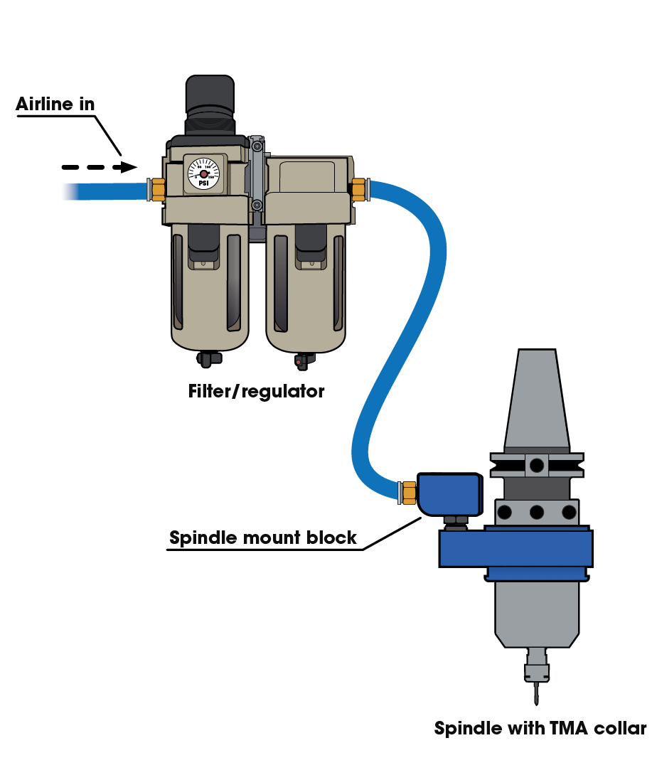
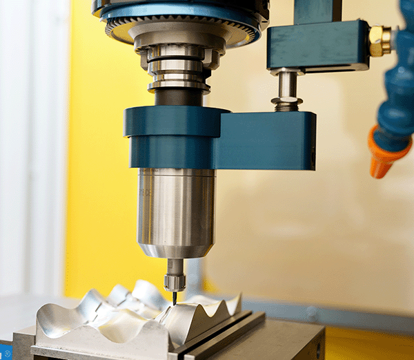
Figure 4: A clean airline from a filter/regulator to an Air Turbine Spindle® with the Tool Changer Mounting Assembly.
Install the supplied spindle mount block by connecting the dedicated clean air line from the included filter/regulator to your spindle as shown in figure 4. We offer many pre-drilled spindle mount blocks for different CNC machine models, and a universal block.
*Install action requires SHCS 10-32 x 0.75” on Haas CNC machines.
Prepare the CNC spindle by performing M19 or spindle orientation. Ensure the TMA nozzle will clear all portions for CNC tool changer guard or machine columns by consulting your CNC manufacturer drawings or verifying all clearances with a mock-up tool. For some gantry machines, the nozzle or O.D. of the TMA collar will not clear the column corner (i.e., All GR type machines require special tool rack on machine table or hand loading).
Note: Once the Air Turbine Spindle® is loaded into your CNC spindle, you should adjust the height of the nozzle screw more to engage the ball valve seal as shown in figure 5. The air flow will turn on the spindle upon coupling.
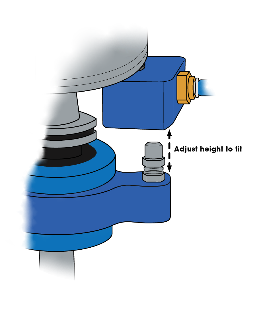
Figure 5: Adjusting the height of the nozzle screw.
Some trial and error may be needed when adjusting the height of your nozzle screws. Do not allow the main spindle drawbar (tool release button) to start unless the connector nozzle goes up into the block inlet hole (Approximately 1/4” (6 mm) up into the inlet hole.).
If the nozzle arm is misaligned from the inlet, remove the Air Turbine Spindle® from CNC spindle taper area and adjust the clocking of the TMA nozzle to properly align it with the inlet hole and re-try loading procedure. Once successfully loaded into the CNC main spindle, turn on the air hose shut-off valve. If the spindle turns on and no air is escaping, then the connector nozzle can be presumed to be set at the correct height. If you hear air escaping, then further adjustment is required.
G-Codes and Spindle Orientation
Ensure the installation was successful by performing a tool change with the over-ride set to the lowest speed several times to observe the loading and unloading of the Air Turbine Spindle® to ensure it engages and operates correctly. Each CNC control has different codes to ensure the CNC main spindle does not turn on while the Air Turbine Spindle® is loaded. It is critical for safety to ensure setup personnel, machine operators, programmers, etc. are all properly notified that the main spindle must remain stationary, except while the CNC machine is doing a tool change. During a tool change, after loading the Air Turbine Spindle® a CNC spindle normally does a spindle orientation or rotation to ensure the drive dogs are aligned prior to loading into the tool changer drum or side mount magazine mechanism. The Tool Changer Mounting Assembly allows a spindle orientation due to its patented collar system.
Troubleshooting your TMA Installation
Air Turbine Spindle® Does Not Turn On
Take a wrench on the connector nozzle screw and turn it counterclockwise to raise the height. Use caution with hands and any clothing that may be near the spindle as your spindle will turn on and rotate at the rated RPM when air is supplied. Once the Air Turbine Spindle® turns on, raise the nozzle screw another small amount and then lock the hex locknut to secure the nozzle in place.
Nozzle is Too High
You will see the blue spindle collar tilt if the nozzle is too high. This may loosen the bottom lock in the spindle collar or allow excessive air to be released from the collar O-rings, which seal the TMA collar to the main flange portion of the TMA collar system. If the nozzle is too high, reverse the procedure to lower the nozzle and re-tighten the locknut so the connector is an accurate fit.
TMA Collar Rotation
A factory set level of resistance (i.e., collar with plunger section to spindle body section) keeps the plunger in place during a tool change, while still allowing the free rotation (i.e., spindle orient). Over time friction may change the stiffness in rotation due to coolant, dust, etc. Ensure there is not too much friction or too little, either will cause the spindle to misload. The tightness of the collar may be adjusted using hex keys. If the spindle collar does not rotate, loosen the collar by adjusting the hex nuts in the spindle collar to allow free rotation at a light pressure without being loose. Your spindle must remain free to rotate while being securely in place.
Maintenance
Your Air Turbine Spindle® must be run at least 10 minutes every 30 days from manufacture date to maintain optimal performance.
Run at least 10 minutes before initial use. The airline must be impeccably clean with no coupling or hose smaller than the minimum internal diameter required for your model as described in figure 2 so that air flow volume is unrestricted.
Purge the airline of contamination before each use. The included 0.3 micron filter extractor regulator combination is a necessary accessory for Air Turbine Spindles® to eliminate impurities in your air supply. Contamination will damage your turbine components and require repair. Filter elements need to be changed periodically and extractor drained in regular maintenance cycles.
Calculating Your New Feed Rate and Cycle Time
You do not need to change the set RPM in your program to operate Air Turbine Spindles® in your CNC machine. Instead, change the feed rate in your program. All Air Turbine Spindles® operate at a constant factory-set fixed speed, and are tested and rated to be within 10% of the designated speed.
The formula in figure 6 below is an approximation for calculating what your new feed rate and cycle time should be. Always consult with an Air Turbine technician for your specific application.
| Calculation Variables | |
| Variable | Example Value |
| Main Spindle RPM | 10,000 RPM |
| Main Spindle Feed Rate | 10 IPM |
| Main Spindle Cycle Time | 60 Minutes |
| Air Turbine Spindle® RPM | 40,000 RPM |
1
40,000 RPM ÷ 10,000 RPM = 4
Divide your Air Turbine Spindle® RPM by the RPM of your main spindle to determine how many times faster the RPM is.
2
10 IPM × 4 = 40 IPM
Calculate your new feed rate when using your Air Turbine Spindle® by multiplying your current feed rate by how many times faster the RPM is.
3
60 Minutes ÷ 4 = 15 Minutes
Calculate your new cycle time by dividing your current cycle time by how many times faster the RPM is.
Figure 6: A set of formulas used to determine your approximate new feed rate and cycle time with an Air Turbine Spindle® using your main spindles RPM, your current feed rate, and current cycle time.
Operation
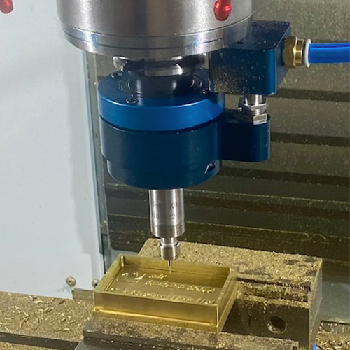
Always monitor the air pressure gauge during operation of your Air Turbine Spindle®. The key to successful high-speed machining and optimized tool performance is to program light passes at very high feed rates. All tools are tested and rated to be within 10% of the designated speed. Start with a light pass observing surface finish quality and gradually step down or increase your rate of advance for optimal cutting conditions. Do not try to cut too aggressively. You will overload your turbine causing your cutting tool to stall or drag in the material. Dragging your tool on the work or a sudden stop will cause stress to the bearings and force the grease out, causing premature failure.
WARNING
Purge the line of contamination and run at least 10 minutes before initial use to ensure the bearing lubrication does not solidify.
Programming your Air Turbine Spindle®
Apart from a few instances, Air Turbine Spindles® will run your normal CAM programs. All you need to do is remove the spindle RPM command (S3000) and the rotation direction command (M3 or M4). At high speed a small concentric speed rated cutting tool should be used with a fast advance using shallow depths of cut. This layering programming technique produces clean cutting action and optimizes tool performance and life.
Spindle Commands
Gradually increase depth of cut to establish optimal cutting conditions. Use M05 on Fanuc type controls to ensure main spindle is turned off. Always ensure main spindle is programmed not to rotate (S0/M05).
Canned Cycles
Beware that on CNC controls the G81, G82, G83 (peck drilling) commands will turn on the machine spindle, even with M05 (spindle stop). In most drilling applications you will not need to peck thanks to the high-speed of your Air Turbine Spindle®. There are several alternative solutions: Some CAM programs will allow you to program to drill without a canned cycle or you could program the path long hand, or you can use macros.
Disable CNC Main Spindle RPM
Program your CNC machine control to allow for normal operation without spindle rotation.
Learn More About Air Turbine Spindles®
Service & Support
Support is always available from our technical team in the USA and Germany. Repair Service is available in Florida and Munich. Call our factory technicians at +1-561-994-0500 or email us at [email protected].