INDEX
1.
2.
3.
4.
5.
6.
7.
8.
9.
10.
11.
12.
When installing and operating your 202HD:
Follow these 12 golden rules to avoid problems, premature failure and ensure successful operation.
Read the User Notes Thoroughly and Comply with Safety Codes
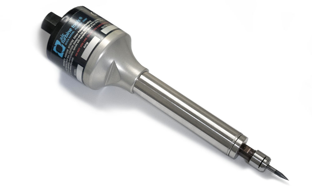
Read, Download and Print the Full User Notes for Air Turbine Motors®
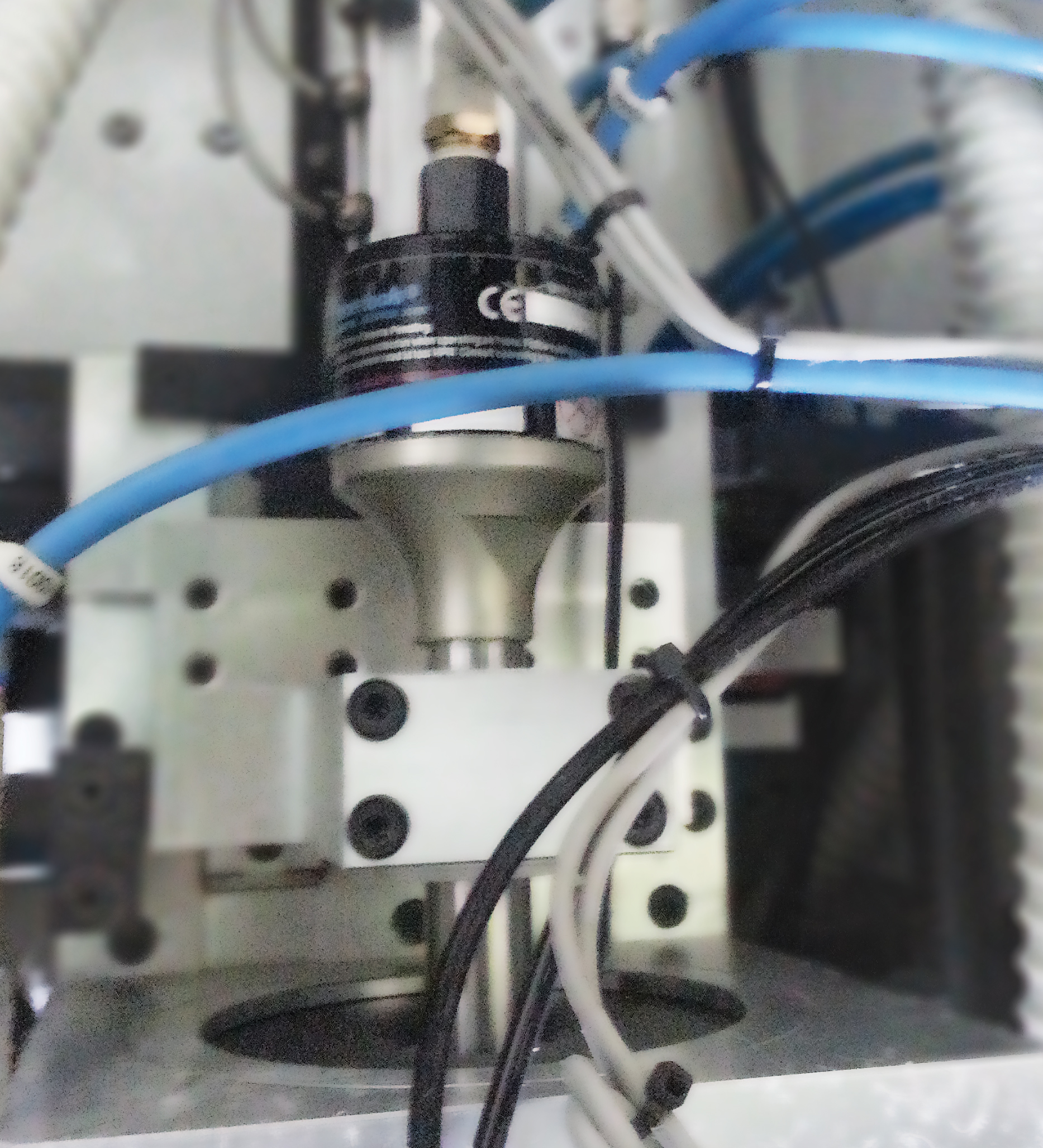
When Mounting Your 202HD, Make Sure the Fixture Is Not Clamped Over the Bearings
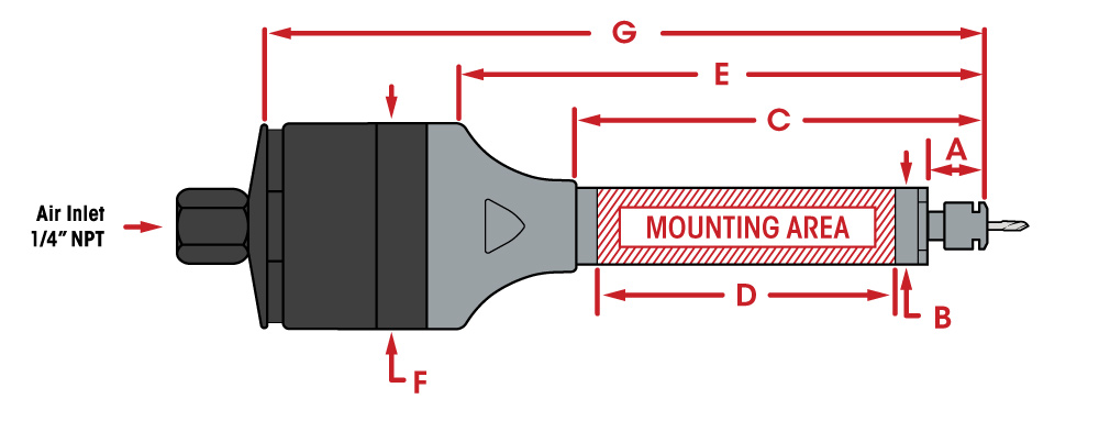
When mounting your 202HD, make sure the fixture is only clamped on the labeled 2″ (50.8 mm) mounting area along the steel barrel. Incorrect positioning or over tightening of the clamp on your Air Turbine Motor® will result in pressure on the bearings and distorting the race. This will cause your 202HD to fail prematurely and will require a repair.
Avoid this frequent installation error by following the dimensional drawing of the 202HD below.
| 202HD Dimensions | |||||
| A | 1.33” (33.84 mm) | D | 2.0” (50.8 mm) | F | Ø 2.0” (50.8 mm) |
| B | Ø 0.74” (18.84 mm) | ||||
| E | 5.35” (135.95 mm) | G | 7.13” (181.1 mm) | ||
| C | 4.27” (108.33 mm) | ||||
| 202HD Dimensions | |
| A | 1.33” (33.84 mm) |
| B | Ø 0.74” (18.84 mm) |
| C | 4.27” (108.33 mm) |
| D | 2.0” (50.8 mm) |
| E | 5.35” (135.95 mm) |
| F | Ø 2.0” (50.8 mm) |
| G | 7.13” (181.1 mm) |
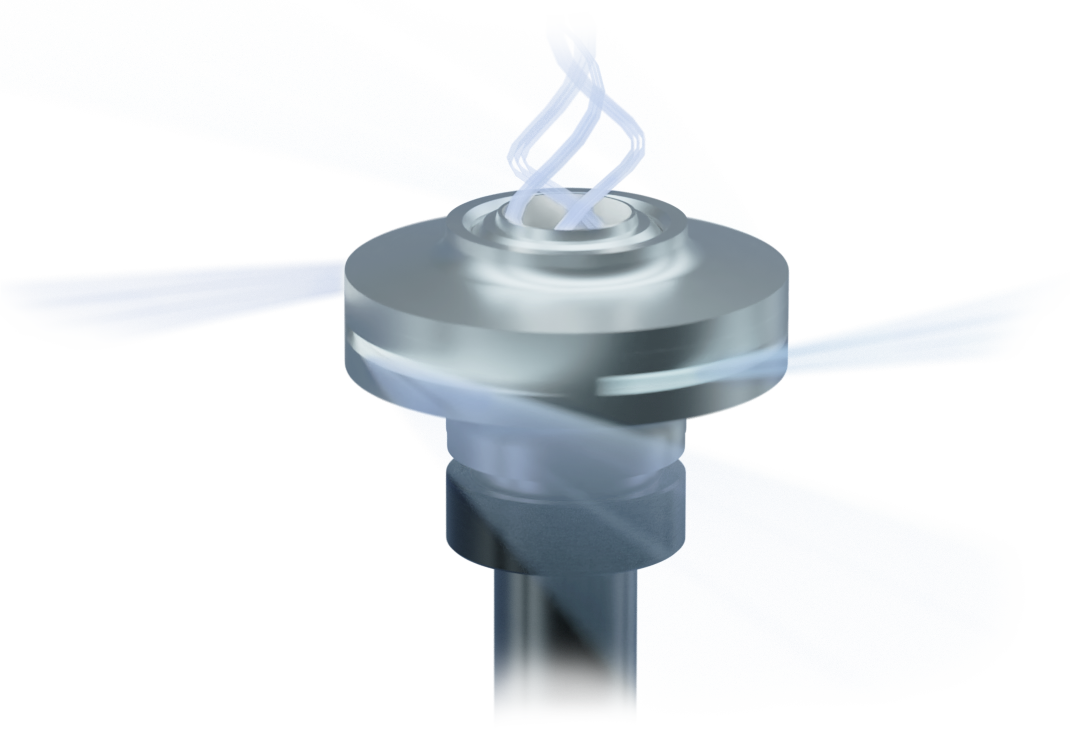
Ensure Sufficient Volume of Compressed Air Flow is Available on Demand
Air flow increases on demand to keep the speed constant when your air powered motor starts to cut. If the air flow volume is insufficient the rotation will suddenly stop. This is called “cavitation” and damages the bearings as the drill dragged through the material. This will cause premature failure.
The table below shows what the air flow volume should look like for your 202HD while idle and working.
| 202HD Air Volume Requirements | ||
| Speed | Air Consumption Idle | Air Consumption Working Flow |
| 30,000 RPM | 10 CFM (4.72 L/s) | 11 CFM (5.19 L/s) - 20 CFM (9.44 L/s) |
| 40,000 RPM | 13 CFM (6.14 L/s) | |
| 50,000 RPM | 14 CFM (6.61 L/s) | |
| 65,000 RPM | ||
| 202HD Air Volume Requirements |
| Speed |
| 30,000 RPM |
| 40,000 RPM |
| 50,000 RPM |
| 65,000 RPM |
| Air Consumption Idle | Air Consumption Working Flow |
| 10 CFM (4.72 L/s) | 11 CFM (5.19 L/s) - 20 CFM (9.44 L/s) |
| 13 CFM (6.14 L/s) | |
| 14 CFM (6.61 L/s) | |
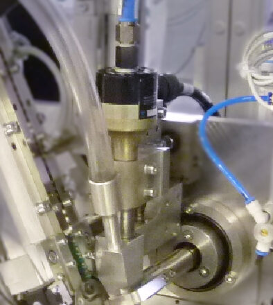
Inlet Pressure Must Be at 90 Psi – 6.2 Bar
Avoid Pressure below 90 psi / 6.2 Bar, which causes the tool to be dragged through the material, causing rapid bearing wear and underpowered performance. More than 100 psi / 6.9 bar pressure will burst the turbine power producer.
Air Pressure and flow must remain constant with no drops under cutting load. Insufficient flow will cause the rotation of your tool to slow or stop suddenly, damaging the bearings. If a drop in psi (bar) occurs below 90 psi (6.2 bar), your compressor may not have enough CFM (L/s) to power the Air Turbine Motor® or there is a flow restriction in the air line.
Do not oil or lubricate. Use dry, clean, oil free 90 psi (6.2 Bar) air supply only.
Make Sure All Hoses, Couplings and Connectors Have At Least 6 mm Internal Diameter
Air flow restrictions, such as air leaks, obstructions, or using hoses or fittings with an internal diameter smaller than 6 mm will cause our pneumatic air motors to have under power performance while your cutting tool drags through the material.
This will cause cavitation to occur and damages the bearings, requiring a repair.
When installing your 202HD, make sure that all fittings, couplings and hoses have an internal diameter that is 6 mm or larger as any connections smaller than the minimum will restrict air flow and reduce power to your 202HD.
Keep the Compressed Air Supply Impeccably Clean and Dry
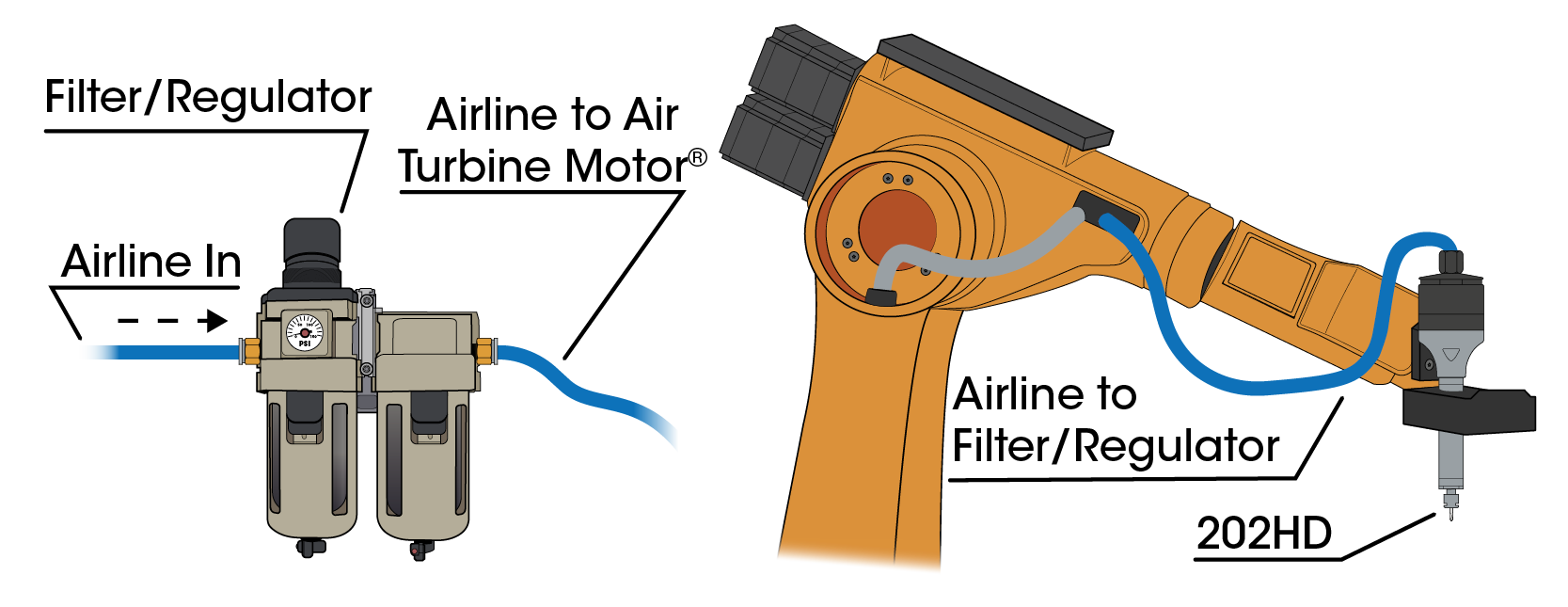
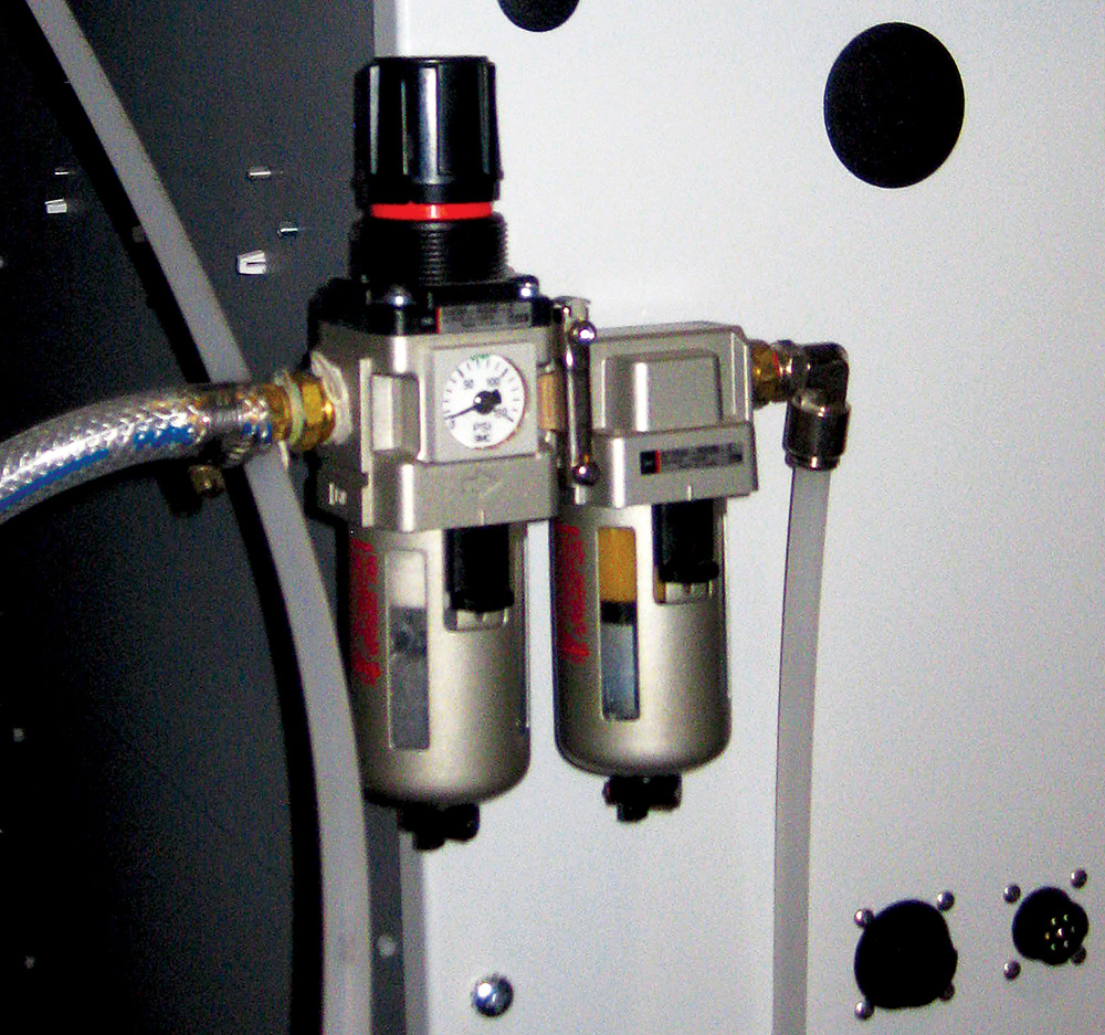
The airline with your 202HD must be kept impeccably clean. Before each initial use, you should purge the line of your air motors to ensure the bearing lubrication does not solidify. You should be using a 0.3 micron filter extractor regulator combination (Part Number: 30003) with your air powered motor in order to eliminate impurities in your air supply.
Contamination will damage your turbine.
Filter elements need to be changed and extractor drained in regular maintenance cycles. You can find information on replacement elements in the accessories section on our website.
Select the Correct Cutting Tool
Double check that your cutting tool is rated for the rotational speed you are using. Your carbide tool must be balanced and truly concentric to operate at the high speeds of 30,000 – 65,000 RPM that the 202HD runs at.
Selecting a cutting tool that is not rated for these speeds will cause unbalanced rotation or overloading, which will result in stress on the bearings and premature failure.

Follow Proper Procedures When Opening and Closing the Collet System
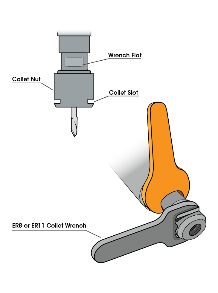
The above shows the correct insertion of both the wrench and the ER8 or ER11 collet wrench used to remove or secure the collet nut.
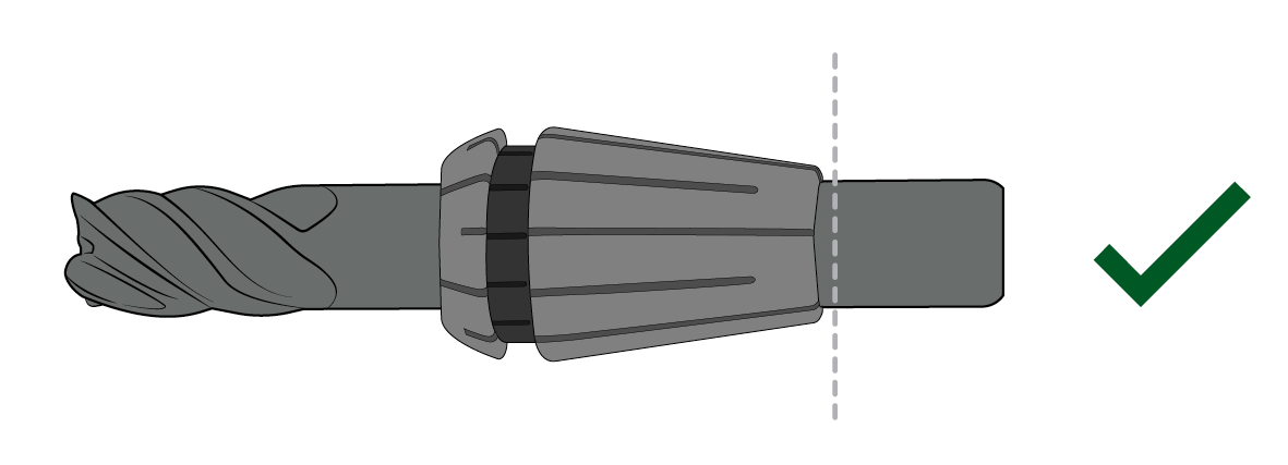
Correct
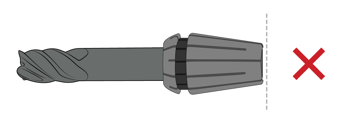
Incorrect
This comparison shows the correct and incorrect way to insert the cutting tool into your collet. Ensure that the cutting tool goes completely through the collet.
| Recommended Torque for ER8 and ER11 Collet Nuts | |||
| Collet Type | Collet Size | ft-lbs | Torco-Fix |
| ER8 | Ø 0.039” (1.0mm) - 0.196” (5.0mm) | 4 | Micro |
| ER11 | Ø 0.039” (1.0mm) - 0.098”(2.9mm) | 7 | Micro, S |
| Ø 0.118”(3.0mm) - 0.256” (7.0mm) | 7 | Micro, S | |
| Recommended Torque for ER8 and ER11 Collet Nuts |
| Collet Type |
| ER8 |
| ER11 |
| Collet Size | ft-lbs | Torco-Fix |
| Ø 0.039” (1.0 mm) - 0.196” (5.0 mm) | 4 | Micro |
| Ø 0.039” (1.0 mm) - 0.098”(2.9 mm) | 7 | Micro, S |
| Ø 0.118”(3.0 mm) - 0.256” (7.0 mm) | 7 | Micro, S |
Avoid these Common Cutting Tool Installation Mistakes

Do Not Over-Extend the Cutting Tool
The stick-out extension length should be no more than 3 times the diameter of your cutting tool. Additionally, the cutting tool must go completely through the collet.
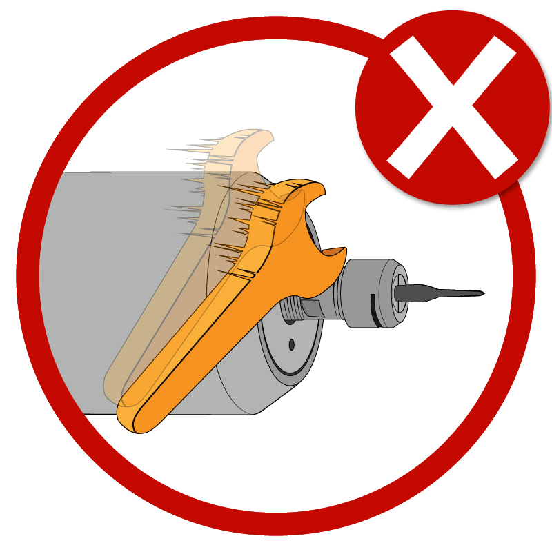
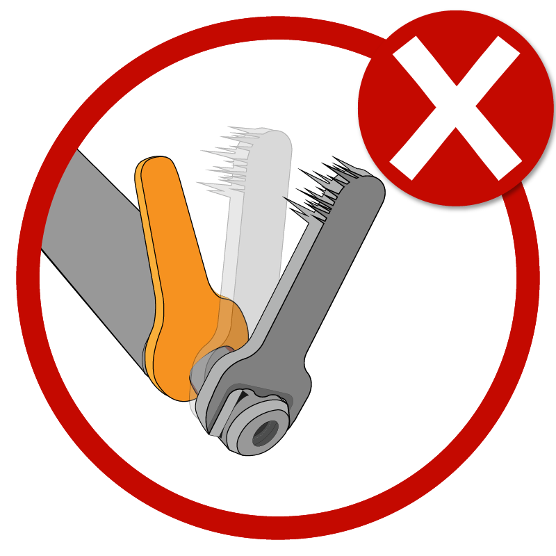
Never Hit the Collet Nut with the Wrench
Always use the provided wrench and collet wrench when opening and closing your ER collet.

Never Use Cutting Tools That Are Not Rated For Your Rotational Speed
Your cutting tool must be concentric and rated for the rotational speed you are using. Using an improper cutting tool will result in premature failure. The 202HD runs at speeds of 30,000 to 65,000 RPM.
Do Not Over Tighten the Collet Nut
Use the torque specified for your collet in the "Recommended Torque" table from the previous section.
Avoid Sudden Stops of the Advance
Avoiding sudden stops of the advance of the automated band of material when a cutting tool or drill is inserted is crucial. Sudden stops will wear down the bearings and potentially blow out the grease. Additionally, stress occurs when the advance of the band is not stopped before the cutting tool or drill enters a rubber band and can cause premature failure.
Do Not Program a Rate of The Plunges and Band Advance too Aggressively
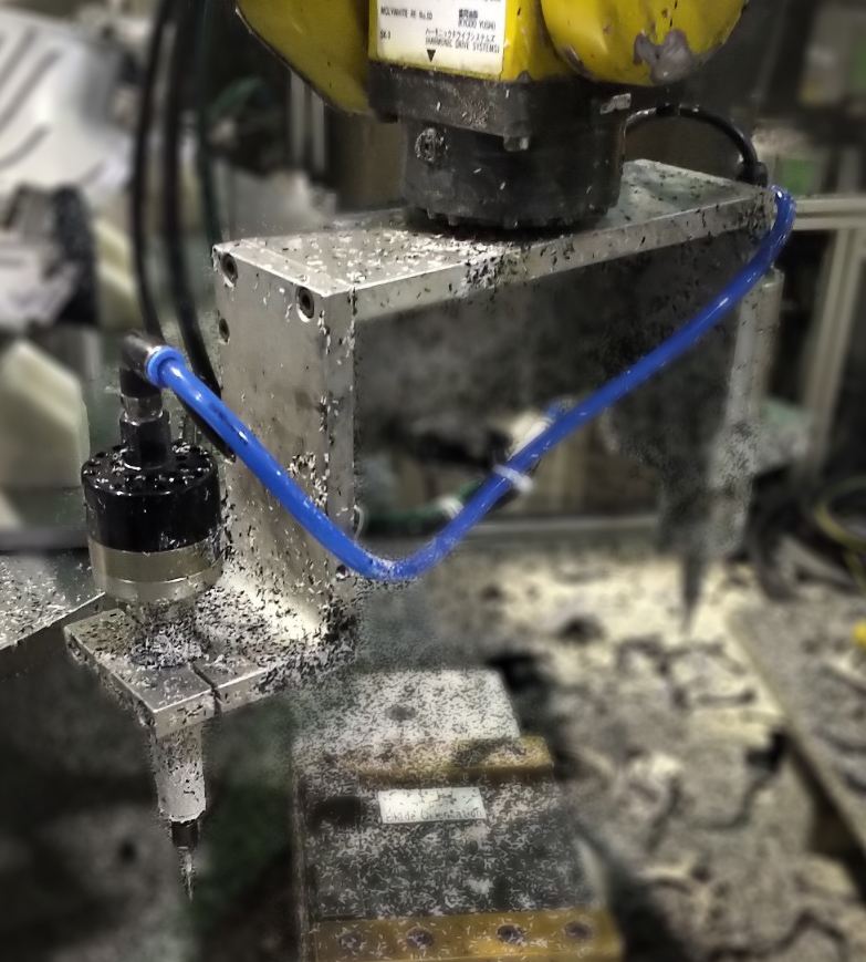
Programming the rate of plunges or advance too aggressively will overburden your air powered motor by causing your cutting tool to stall out or drag in the material. This will result in your 202HD wearing out faster, and requiring repair.
To optimize tool performance, it is recommended to program light passes at very high feed rates. Start with a light pass and observe the surface finish quality. Then gradually step down or increase your rate of advance as needed to obtain optimal cutting conditions.
Prevent Heat From Transferring to Your 202HD When Drilling
After extrusion, the material should go through a cooling process before you begin drilling with your air powered motor. This is to prevent heat from transferring from the material to the cutting tool and the bearings. This cooling process will reduce the risk of premature failure.
Contact us to discuss your application!
There's more to Air Turbine Motors®
Service & Support
Support is always available from our technical team in the USA and Germany. Repair Service is available in Florida and Munich. Call our factory technicians at +1-561-994-0500 or email us at [email protected].
